
Engineering a 25-Slot ESD EVA Foam Divider—from Component Protection to Packed Volume
A long-format handling insert for a North American electronics manufacturer
At nearly 1.3 meters long, this divider was not simply a foam-cutting job. Static control, repeated slot geometry, operator handling, production consistency, and export packing all had to work as one system. The project delivered 50 custom 25-slot ESD EVA dividers and reduced the final packed volume to 4.4 m³ through a two-piece nesting configuration.
|
50 finished inserts |
25 positions per insert |
1,295.4 mm finished length |
4.4 m³ final packed volume |
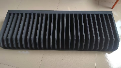
Finished 25-slot ESD EVA foam divider, front view
|
What the “approximately 37%” figure means The final packing record shows 4.4 m³. The 7.0 m³ figure was an early quotation-stage estimate—not a second, equally mature packing trial. The difference is approximately 37%, demonstrating a substantial reduction in expected occupied volume for this project. It is not a guaranteed freight-cost reduction; actual charges depend on carton dimensions, gross weight, mode, route, and carrier rules. |
Project at a Glance
|
Project item |
Confirmed information |
|
Customer |
North American electronics manufacturer (anonymous) |
|
Product |
Custom ESD EVA foam insert / divider |
|
Finished size |
1295.4 × 457.2 × 177.8 mm |
|
Divider geometry |
25 positions at 38.1 mm pitch; chamfered walls and a stepped side profile |
|
Material |
Black, closed-cell, permanently static-dissipative EVA; 38 ± 5 Shore C grade |
|
Quantity and packing |
50 pieces; 2 nested pieces per carton; 25 cartons; 4.4 m³ final volume |
Why This Was More Than a Foam-Cutting Job
The insert sat at the intersection of four constraints. The electronic parts needed a defined dissipative path. Twenty-five positions had to remain consistent over a long format. The walls had to stand upright without turning contact into a hard interface. And because foam is light but bulky, export cost could be driven by dimensional or volumetric weight. Optimizing one requirement in isolation could easily create a problem elsewhere.
· ESD risk: Conventional cushioning foam does not normally provide a controlled charge-dissipation path, and black color alone does not prove ESD performance.
· Fit risk: Pitch defines the repeated locations; it does not define the usable slot width. Clearance, compression, tolerances, and contact surfaces still require drawing or sample review.
· Handling risk: Walls that are too soft can lean or collapse. Walls that are too firm can increase insertion force and contact stress.
· Logistics risk: A large divider can consume substantial shipping volume. Nesting direction, wall protection, carton size, and load efficiency need to be considered before production.
Four Engineering Decisions
1. Define the ESD requirement before selecting the foam
The project used black, closed-cell ESD EVA in which the carbon-black compound is blended into the resin rather than applied as a surface coating. Dissipative performance therefore exists through the material body. Normal surface wear does not remove an entire ESD layer in the way that abrasion can remove a coating, which is useful for repeated loading and work-in-process handling.
|
Property |
TDS value |
Design relevance |
Production-acceptance note |
|
Surface resistance |
1.0 × 10⁵–1.0 × 10⁹ Ω |
Provides a dissipative range for electronics packaging |
Agree the method, electrodes, applied voltage, conditioning, temperature/humidity, sampling, and reporting |
|
Static decay |
< 2.0 s, ±1000 V to ±100 V |
Allows accumulated charge to decay more quickly |
Confirm the test standard and specimen conditions |
|
Hardness |
38 ± 5 Shore C |
Balances wall support and contact cushioning |
Final choice also depends on part mass, contact area, insertion force, and drop requirements |
|
Density |
65 ± 5 kg/m³ |
Adds body and stability to a long structure |
Density alone is not a substitute for cushioning data or transport validation |
|
Compression set |
≤ 5% |
Supports recovery under the specified test conditions |
Confirm compression, temperature, and duration |
|
Water absorption |
≤ 0.5% by volume |
Closed cells help limit water uptake |
Does not by itself prove cleanliness, low ionic content, low outgassing, or optical compatibility |
|
Evidence boundary These figures are typical/specified values from the project material TDS; they are not presented here as measured results for every production lot. Projects governed by an ESD standard or an internal control plan should define the test method, conditioning, sampling, acceptance limits, and shipment documentation during quotation and first-article approval. |
2. Use geometry to remove uncertainty from loading
Twenty-five separate positions prevent part-to-part contact, while the 38.1 mm pitch establishes a repeatable loading pattern. Chamfered wall entrances reduce edge interference, and the stepped side profile preserves support while creating clearance along the insertion path. The purpose of the geometry is not complexity for its own sake; it is to prevent operators from adding temporary pads, forcing walls apart, or repeatedly realigning parts.
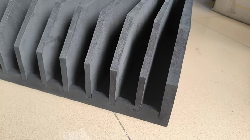
Close-up: repeated positions, chamfered entrances, and long-format side support
|
Pitch is not slot width For a new application, define the maximum part envelope, usable slot width, wall thickness, intended clearance or compression, no-touch surfaces, and allowable insertion force. Without those inputs, a 38.1 mm pitch cannot be assumed to fit another product. |
3. Turn repeated long-format geometry into a repeatable process
The customer’s 3D design was translated into separate operations for large-format blank preparation, repeated-position forming, chamfers, and the stepped profile. A reusable custom cutting die established a repeatable production reference for the critical profile.
· First-article review: Check the overall outline, position count, pitch, end geometry, surface condition, and packing orientation.
· Production control: Inspect defined critical dimensions and appearance; verify ESD properties at the agreed method and frequency.
· Repeat-order consistency: Reuse the dedicated die for the same design, but review any product, drawing, or tolerance change before assuming the tooling still applies.
· Recommended records: Controlled drawing revision, first-article results, material lot or certificate, inspection data, and engineering-change history.
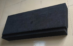
Rear view: the long base and multi-operation construction form a single handling structure
4. Engineer export packing before the product reaches the carton
Two finished inserts were oriented and nested in each carton so that they shared part of the same space without directly crushing the divider walls. Fifty pieces were packed two per carton, for 25 cartons and a final total volume of 4.4 m³. Compared with the early 7.0 m³ estimate, the final configuration occupied approximately 2.6 m³ less volume.
|
Packing metric |
Early estimate |
Final configuration |
|
Order quantity |
50 pieces |
50 pieces |
|
Packing method |
Conventional estimate |
2 nested pieces per carton |
|
Carton count |
— |
25 cartons |
|
Total volume |
7.0 m³ |
4.4 m³ |
|
Volume per insert |
Approx. 0.140 m³ |
Approx. 0.088 m³ |
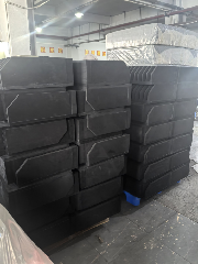
Finished inserts arranged in the nesting orientation before final cartoning
Evidence Matrix: Confirmed Here vs. Defined for the Next Project
|
Topic |
Confirmed in this case |
Define for a new project |
|
Material |
TDS property range; closed-cell ESD EVA; 38 ± 5 Shore C |
Applicable standard; method and conditioning; lot reporting; cleanliness and contamination limits |
|
Geometry |
Overall size; 25 positions; 38.1 mm pitch; chamfers and stepped profile |
Usable slot width; critical tolerances; clearance/compression; no-touch surfaces; insertion force |
|
Manufacturing |
Dedicated tooling; staged forming; finished-part geometry and appearance checks |
FAI criteria; sampling plan; gauges/fixtures; traceability; change control |
|
Transport |
2 pieces per carton; 25 cartons; 4.4 m³ final volume |
Carton dimensions and gross weight; stacking; drop, vibration, compression, and climate profile |
|
Service life |
TDS compression-set performance |
Target cycles; cleaning; resistance recheck after wear/contamination; retirement criteria |
Project Results
· Produced and packed 50 long-format custom ESD EVA dividers.
· Created 25 defined positions per insert, with chamfered walls and a stepped profile to support loading.
· Packed two nested inserts per carton: 25 cartons and 4.4 m³ final volume.
· Reduced occupied volume by approximately 37% versus the 7.0 m³ early estimate; this is not a guaranteed freight-cost percentage.
· Established reusable tooling and a defined process for repeat production of the same design.
The transferable lesson is the engineering sequence: start with the packaged part, ESD control plan, operator motion, and shipping environment; then work backward to material, hardness, geometry, process controls, validation, and carton configuration. Do not start with a generic foam grade and look for a use case afterward.
Where This Approach Fits—and Where More Evaluation Is Needed
|
Potential fit |
Additional evaluation needed |
|
PCBs/PCBAs, modules, sensors, connectors, and electromechanical parts that need separation and handling |
Exposed optical surfaces or parts highly sensitive to carbon transfer or particulates |
|
Repeated loading, work-in-process handling, internal logistics, and export shipment |
Cleanroom, low-ionic, low-outgassing, strict odor, or chemical-compatibility requirements |
|
Light- to medium-mass parts that can be located by foam divider walls |
High-mass, high-center-of-gravity, very low-fragility-limit, or severe shock-isolation applications |
|
Long foam structures that can be nested to reduce shipping volume |
Systems requiring a moisture barrier, shielding bag, desiccant, or sealed environmental protection |
Eight Inputs for a Useful RFQ
1. 2D or 3D part/insert drawings, maximum and minimum dimensions, and critical tolerances;
2. part mass, center of gravity, fragile areas, and no-touch surfaces;
3. parts per insert, loading direction, and the expected handling sequence;
4. applicable ESD standard, resistance/decay targets, and shipment-reporting requirements;
5. temperature/humidity, cleanliness, chemical, particle, and odor restrictions;
6. shipping mode and route, available carton/tote dimensions, and validation requirements;
7. target reuse cycles, cleaning method, and retirement criteria; and
8. prototype quantity, production quantity, annual demand, and required delivery cadence.
|
Ready for an engineering review? Send the drawing, part mass and sensitive surfaces, ESD requirement, loading quantity, order volume, and shipping method. The response should include a material/hardness recommendation, geometry risks, tolerances and validation items to confirm, and a packed-volume concept—not only a foam price calculated from outside dimensions. |
Frequently Asked Questions
Does “permanently static-dissipative” mean the foam never needs to be retested?
No. It means the dissipative ingredient is present through the material rather than only in a surface coating. Actual resistance can still be affected by lot variation, humidity, contamination, wear, and test method. Define incoming, first-article, or shipment testing according to the control plan.
Is a surface-resistance range of 1.0 × 10⁵–1.0 × 10⁹ Ω suitable for every electronic part?
Not automatically. Suitability depends on the customer’s ESD control plan, device sensitivity, packaging stage, and applicable standard. The test method must also be specified.
Is 38° Shore C always the best hardness?
No. It balanced wall support and cushioning in this project. Part mass, slot width, wall height, contact area, insertion force, and transport severity can lead to a different selection.
Will nesting always save 37% in freight cost?
No. This case reduced final occupied volume by approximately 37% versus an early estimate. Freight cost depends on dimensions, weight, mode, route, load utilization, and carrier rules.
What should be validated after prototyping?
At minimum: part fit, loading path, insertion force, sensitive-surface contact, wall stability, and critical dimensions. For transport use, evaluate the complete product–foam–carton system for drop, vibration, compression, and environment as required by part fragility and the distribution route.
INTERNAL PUBLISHING NOTES
Recommended SEO Fields (not part of the public article body)
|
Publishing field |
Recommended copy |
|
Page title |
Custom 25-Slot ESD EVA Foam Divider Case Study | Electronics Packaging |
|
Meta description |
See how a 25-slot ESD EVA foam divider combined material selection, loading geometry, repeatable tooling, validation planning, and nested export packing for 50 electronics-handling inserts. |
|
URL slug |
esd-eva-foam-divider-case-study |
|
Primary keywords |
ESD EVA foam inserts; ESD foam divider; custom electronics packaging foam |
|
Suggested image ALT |
25-slot custom ESD EVA foam divider for electronics handling |