
For manufacturing engineers, sourcing professionals and product engineers
From Laminated Foam to One-Piece Heat-Pressed Construction
Electronic assemblies, PCBAs and precision components require more than ESD protection during work-in-process movement. They also need cushioning, controlled positioning and a packaging format that can withstand repeated handling. Conventional foam trays are often built by cutting and bonding multiple layers. This method is useful for prototypes and low volumes, but long-term use may require additional control of adhesive joints, layer alignment, lifted edges and exposed cut surfaces.
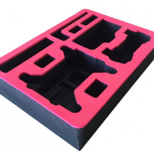
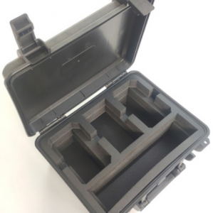
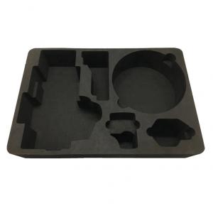
One-piece heat-pressed ESD EVA trays use pre-foamed closed-cell EVA sheet formed between matched male-and-female molds. The base, sidewalls, dividers and positioning cavities become one integrated structure. There are no laminated structural layers and no separately bonded bottom panel. Cushioning, positioning, stable stacking and automation features can therefore be incorporated into a single tray.
How the Process Works
The production sequence is: ESD EVA foam-sheet preheating → matched-mold heat pressing → pressure holding → cooling and setting → trimming or die cutting → inspection.
This is not an in-mold foaming process. The EVA is already foamed before it enters the mold. Heat softens the sheet so that the matched tool can create the three-dimensional geometry. Heating uniformity, compression ratio, holding time and cooling conditions affect cavity definition, springback, dimensional stability and local material performance.
Engineering Value
• One-piece construction — no structural adhesive layers, reducing the risk of delamination and edge separation.
• Three-dimensional customization — deep cavities, dividers, support pads, clearance zones, finger access and poka-yoke features can be formed.
• ESD protection — material-integrated electrical performance, with surface and volume resistance values of 10⁴–10⁸ Ω.
• Stable stacking — dedicated load-bearing rims can transfer stack loads away from the stored components.
• Automation compatibility — locating datums, pick-up areas, orientation features and sensor-access zones can be incorporated.
• Reusable handling — the closed-cell structure combines cushioning, low water absorption and wear resistance for production circulation.
Demonstrated Production Capability with Existing Molds
The following trays represent three different demonstrated limits from existing molds: maximum molded height, maximum tray net weight and maximum length/width. These values come from separate designs and should not be interpreted as simultaneous limits for a single tray. New projects remain subject to engineering review based on cavity depth, projected area, compression distribution and equipment capacity.
|
Capability |
Demonstrated Existing-Mold Reference |
|
Maximum molded height |
115 mm |
|
Maximum tray net weight |
1.967 kg (1,967 g) |
|
Largest existing mold size |
700 × 680 mm |
|
Material hardness |
Approx. Shore C 38° |
|
ESD resistance performance |
Surface and volume resistance: 10⁴–10⁸ Ω |
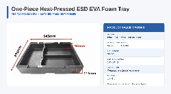
Figure 1. Maximum molded-height reference: 545 × 396 × 115 mm, 90 mm cavity depth and 1,445 g net weight.
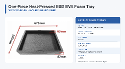
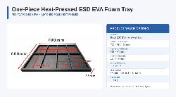
Figure 3. Largest existing mold-size reference: 700 × 680 × 35 mm, 665 × 640 mm internal area and 1,600 g net weight.
Design and Selection Considerations
Tray design should not simply reproduce the component outline. Engineering inputs should include the maximum component envelope, weight and center of gravity, approved support surfaces, no-contact zones around PCBAs and connectors, cable length and minimum bend radius, and the intended manual or robotic loading method. Cavities should also include appropriate tolerance, finger clearance and a controlled removal path.
Stackability must be implemented through a defined load path. The upper tray should transfer its load through the perimeter frame or dedicated supports rather than through the stored component. Loaded tray weight, stack height, storage duration and acceptable compression deformation should be established during project review.
Understanding ESD Performance and Long-Term Stability
The ESD function is integrated into the EVA material rather than applied as a temporary surface coating. Finished trays can be tested in both the surface direction and through the material thickness, with surface and volume resistance values of 10⁴–10⁸ Ω using weighted electrodes. The agreed specification should also define electrode arrangement, test voltage, environmental conditions and sampling method.
Because the conductive and static-dissipative function extends through the material, the ESD performance does not naturally diminish with service time under normal use in the way that a temporary coating or short-term antistatic treatment may. Periodic verification is still appropriate after severe contamination, mechanical damage or exposure to extreme service conditions.
The tray can be used as a packaging and handling element within an ANSI/ESD S20.20 control program. Overall program conformity also depends on personnel grounding, work surfaces, transport paths and verification frequency.
Applications
One-piece heat-pressed ESD EVA trays are suitable for PCB assemblies, electronic modules, sensors, connectors, automotive electronics, precision-machined parts, optical components and work-in-process handling. When cushioning and controlled positioning are the primary requirements, the tray can be used directly as a reusable handling solution.
Conclusion
A one-piece heat-pressed ESD EVA tray is more than simple foam packaging. It is a reusable production-handling tool engineered around the component, workstation and material flow. By integrating ESD protection, cushioning, positioning, stable stacking and automation interfaces into a non-laminated structure, it provides a practical option for protecting precision components throughout production.
Discuss your application: info@yufapolymer.com
Send us your component sample, drawing or 3D data. We can first review suitable options from our existing molds or develop a dedicated matched-mold design for your component and production process.