
Flat trays, divided trays, perforated trays, oven-rated trays — screen by usable internal size and tray depth first, no rush to new tooling
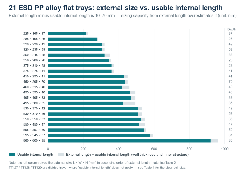
Figure 1 Yufa’s 21 existing ESD PP alloy flat trays: external size vs. usable internal length and tray depth (in ascending order of external length). The chart is for screening only; dimensions and structures are subject to the corresponding product code.
01 Two main lines | 02 Flat trays | 03 Divided trays | 04 Base pattern | 05 Sizes | 06 Filling the gap | 07 New tooling | 08 Resistance
Customers asking about ESD trays describe them even more vaguely than they describe boxes: the single word “tray” may mean a shallow tray for line transfer, a divided tray for component positioning, a perforated tray for washing and drying, or an oven-rated tray for 150 °C baking. All four types coexist in Yufa’s current product line — 51 models in total, with external lengths from 150 mm to 960 mm across two ESD material families.
Rather than entering a new-tooling quotation process from the outset, the more efficient route is to take the product dimensions, the weight per part, the loading method, whether washing and drying apply and whether temperature resistance is needed, screen them against the existing specifications, and then complete the solution with dividers, foam or a liner.
|
Key takeaway | Separate “flat tray” from “divided tray” first. Flat trays account for 44 models, where the usable internal size and the tray depth come first. There are only 7 divided trays, and there the clear cell size must be fixed before the total cell count — reverse the order and the rework takes a completely different form. |
1. What customers are really looking for when they search “ESD tray”
Trays are the most varied category in the injection-moulded series: across 51 models the external length runs from 150 mm to 960 mm and the tray depth from 16 mm to 100 mm, covering everything from a small open box to a large 960 × 600 panel. When a customer types “ESD tray” into the search box, what they have in mind is usually not a particular model but a scenario that has not yet taken shape.
Defining the scenario first is far more useful than looking at model codes first:
• Line transfer: the product moves between processes as a full tray, so the questions are tray depth, whether trays can be stacked, and whether a trolley is involved.
• Component positioning: every part has a fixed place, so the questions are the clear cell size and the cell count.
• Washing and drying: the whole tray passes through water or air, so the questions are the base pattern and drainage.
• High-temperature processes: the whole tray goes into an oven, so the question is the temperature resistance of the material.
All four types have matching models in the current range, but the fields you screen on are completely different — use the wrong field and you keep trialling models that merely look close enough.
2. Separate the two main lines first: flat trays and divided trays
The 51 trays split along a single line into two groups: those with divisions in the base and those without (Table 1).
|
Type |
Models available |
Typical cell count |
Main application |
|
Flat tray (no divisions) |
44 |
— |
Process transfer, batch placement, washing and drying, oven baking |
|
Divided tray |
7 |
4 / 6 / 8 / 10 / 20 / 80 |
Single-part positioning, anti-collision, counting |
The two lines are selected in the opposite order. For flat trays, look at the usable internal size and tray depth first; cell count does not enter into it. For divided trays, the clear cell size must be fixed first — the 400 × 325 × 29 tray carries 20 cells of only 64 × 64 × 20 mm each, so if the product is an 80 mm square module this model is ruled out from the start, however close it is to the external size you had in mind.
3. Flat tray overview: 21 in PP alloy + 23 in PP
First the 21 PP alloy flat trays, all in ESD PP alloy with a surface resistance of 10⁴ – 10⁸ Ω, listed in ascending order of external length.
|
Product code |
External size (mm) |
Usable internal size (mm) |
Net weight (kg) |
Features |
|
IMT-PPA-225-165-37 |
225 × 165 × 37 |
215 × 155 × 32 |
0.18 |
Slots in the tray wall; optional dividers |
|
IMT-PPA-285-195-26 |
285 × 195 × 26 |
275 × 185 × 23 |
0.26 |
— |
|
IMT-PPA-320-230-42 |
320 × 230 × 42 |
305 × 218 × 37 |
0.39 |
— |
|
IMT-PPA-320-235-58 |
320 × 235 × 58 |
305 × 220 × 52 |
0.47 |
— |
|
IMT-PPA-350-245-88 |
350 × 245 × 88 |
320 × 215 × 80 |
0.64 |
Deep tray |
|
IMT-PPA-356-286-26 |
356 × 286 × 26 |
345 × 275 × 22 |
0.48 |
— |
|
IMT-PPA-375-310-28 |
375 × 310 × 28 |
360 × 293 × 22 |
0.51 |
— |
|
IMT-PPA-375-275-41 |
375 × 275 × 41 |
360 × 260 × 35 |
0.51 |
— |
|
IMT-PPA-450-295-41 |
450 × 295 × 41 |
430 × 280 × 35 |
0.72 |
— |
|
IMT-PPA-450-295-70 |
450 × 295 × 70 |
435 × 280 × 62 |
1.08 |
Deep tray |
|
IMT-PPA-460-315-40 |
460 × 315 × 40 |
420 × 295 × 30 |
0.73 |
Optional dividers |
|
IMT-PPA-495-395-40 |
495 × 395 × 40 |
465 × 365 × 34 |
0.91 |
— |
|
IMT-PPA-495-495-33 |
495 × 495 × 33 |
470 × 470 × 29 |
1.60 |
Rated for 150 °C oven baking |
|
IMT-PPA-495-380-35 |
495 × 380 × 35 |
425 × 315 × 30 |
0.68 |
— |
|
IMT-PPA-530-370-42 |
530 × 370 × 42 |
510 × 350 × 34 |
1.22 |
Slots in the tray wall |
|
IMT-PPA-530-370-56 |
530 × 370 × 56 |
510 × 350 × 50 |
1.07 |
— |
|
IMT-PPA-550-550-33 |
550 × 550 × 33 |
525 × 525 × 30 |
1.45 |
— |
|
IMT-PPA-550-455-47 |
550 × 455 × 47 |
515 × 415 × 43 |
1.58 |
— |
|
IMT-PPA-555-357-50 |
555 × 357 × 50 |
540 × 340 × 46 |
1.15 |
— |
|
IMT-PPA-595-545-37 |
595 × 545 × 37 |
575 × 535 × 32 |
1.92 |
— |
|
IMT-PPA-960-600-35 |
960 × 600 × 35 |
920 × 570 × 25 |
7.00 |
Rated for 150 °C oven baking |
Three selection patterns can be read from Table 2:
• Usable internal length is generally 10–40 mm shorter than the external length, and on one model the loss reaches 70 mm. The largest differences are on 495 × 380 (70 mm) and on 460 × 315 and 960 × 600 (40 mm each) — estimating capacity from external dimensions will noticeably overestimate it on these models.
• Tray depth spans a far wider range than external length. The same 450 × 295 base exists as a 70 mm deep tray and a 41 mm shallow tray, and the 350 × 245 deep tray reaches 88 mm. Tray depth often decides the outcome earlier than length and width do.
• Two models are rated for 150 °C: 495 × 495 × 33 and 960 × 600 × 35, both intended for baking processes. The 960 × 600 × 35 has a net weight of 7.0 kg, the heaviest in the whole range, so the handling method has to be considered at the same time.
Next, the 23 PP flat trays, in ESD PP with a surface resistance of 10⁵ – 10⁹ Ω. This group spans an even wider size range, from the small 150 × 98 open box up to the large 720 × 510 panel.
|
Product code |
External size (mm) |
Usable internal size (mm) |
Net weight (kg) |
Features |
|
IMT-PP-150-98-55 |
150 × 98 × 55 |
127 × 80 × 45 |
0.071 |
Open box (No.1) |
|
IMT-PP-210-135-65 |
210 × 135 × 65 |
175 × 115 × 55 |
0.140 |
Open box (No.2) |
|
IMT-PP-227-167-37 |
227 × 167 × 37 |
220 × 160 × 35 |
0.190 |
No slots |
|
IMT-PP-260-175-75 |
260 × 175 × 75 |
215 × 153 × 70 |
0.203 |
Open box (No.3) |
|
IMT-PP-300-205-85 |
300 × 205 × 85 |
265 × 178 × 80 |
0.295 |
Open box (No.4) |
|
IMT-PP-319-232-40 |
319 × 232 × 40 |
310 × 222 × 35 |
0.358 |
— |
|
IMT-PP-373-250-65 |
373 × 250 × 65 |
350 × 220 × 60 |
0.369 |
— |
|
IMT-PP-380-240-100 |
380 × 240 × 100 |
335 × 213 × 90 |
0.461 |
Open box (No.5) |
|
IMT-PP-380-310-28-NP |
380 × 310 × 28 |
360 × 290 × 23 |
0.440 |
No holes (No.11) |
|
IMT-PP-380-310-28-RH |
380 × 310 × 28 |
360 × 290 × 23 |
0.440 |
Perimeter holes (No.11) |
|
IMT-PP-380-310-20-NP |
380 × 310 × 20 |
360 × 290 × 15 |
0.450 |
No holes (No.12) |
|
IMT-PP-380-310-20-HP |
380 × 310 × 20 |
360 × 290 × 15 |
0.450 |
Fully perforated (No.12) |
|
IMT-PP-380-310-20-RH |
380 × 310 × 20 |
360 × 290 × 15 |
0.450 |
Perimeter holes (No.12) |
|
IMT-PP-395-295-30 |
395 × 295 × 30 |
380 × 280 × 19 |
0.426 |
Adjustable |
|
IMT-PP-434-291-76 |
434 × 291 × 76 |
408 × 265 × 70 |
0.452 |
— |
|
IMT-PP-436-288-48 |
436 × 288 × 48 |
400 × 265 × 43 |
0.479 |
— |
|
IMT-PP-455-300-55 |
455 × 300 × 55 |
435 × 280 × 50 |
0.690 |
— |
|
IMT-PP-595-540-35 |
595 × 540 × 35 |
575 × 535 × 30 |
2.000 |
— |
|
IMT-PP-600-450-40 |
600 × 450 × 40 |
575 × 445 × 23 |
1.500 |
— |
|
IMT-PP-600-600-30 |
600 × 600 × 30 |
575 × 575 × 15 |
2.100 |
— |
|
IMT-PP-650-650-40 |
650 × 650 × 40 |
640 × 640 × 20 |
2.500 |
— |
|
IMT-PP-706-545-50 |
706 × 545 × 50 |
695 × 539 × 45 |
1.970 |
— |
|
IMT-PP-720-510-48 |
720 × 510 × 48 |
690 × 500 × 25 |
2.500 |
— |
Three points in the PP series deserve separate mention:
• The 380 × 310 group offers the complete set of base options: at 28 mm depth there are two models, NP (no holes) and RH (perimeter holes); at 20 mm depth there are three, NP (no holes), HP (fully perforated) and RH (perimeter holes) — under a single external size, the base pattern is independently selectable.
• Five models from 150 × 98 to 380 × 240 are labelled Open box: vertical walls with no rim, suitable as small line-side parts boxes but not for stacking.
• 395 × 295 × 30 is the only model marked adjustable: the cells can be rearranged on site, suiting processes where the product specification changes frequently.
4. Divided trays: 7 models — the single cell first, then the total cell count
There are only 7 divided trays, with cell counts of 4, 6, 8, 10, 20, 80 and 80. They fall into two material families: four PP models providing 4–10 large cells, and three PP alloy models providing 20-cell and 80-cell arrays.
|
Product code |
External size (mm) |
Cells |
Clear cell size (mm) |
Net weight (kg) |
|
IMT-PP-510-290-20-D4 |
510 × 290 × 20 |
4 cells |
250 × 140 × 10 |
0.500 |
|
IMT-PP-380-315-30-D6 |
380 × 315 × 30 |
6 cells |
180 × 100 × 22 |
0.432 |
|
IMT-PP-375-310-28-D8 |
375 × 310 × 28 |
8 cells |
145 × 89 × 18 |
0.470 |
|
IMT-PP-370-290-20-D10 |
370 × 290 × 20 |
10 cells |
140 × 70 × 10 |
0.369 |
|
IMT-PPA-400-325-29-D20 |
400 × 325 × 29 |
20 cells |
64 × 64 × 20 |
0.740 |
|
IMT-PPA-315-202-16-D80 |
315 × 202 × 16 |
80 cells |
36 × 17 × 4 |
0.290 |
|
IMT-PPA-356-282-20-D80 |
356 × 282 × 20 |
80 cells |
40 × 24 × 6 |
0.500 |
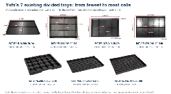
Figure 2 Yufa’s 7 existing divided trays (from fewest to most cells). The red annotations in the product images show the tray outline and the clear cell size; model and parameters are as given in Table 4.
Three patterns:
• Cell count and clear cell size are inversely related. Four cells give a cell of 250 × 140 × 10 mm, while 80 cells leave only 36 × 17 × 4 mm — the latter suits chip components such as 0402 and 0603, or pins and small hardware.
• Cell depth is generally less than tray depth. The 10-cell tray is 20 mm deep while its cells are only 10 mm; the 20-cell tray is 29 mm deep with 20 mm cells. When calculating whether a part fits, use the cell depth, not the tray depth.
• Divided trays do not need the “usable internal size” check. Table 4 therefore gives no overall internal size, only the clear cell size — and that is the test the customer actually has to pass.
5. Choosing the base pattern: no holes / fully perforated / perimeter holes
Only the 380 × 310 group offers several base forms (two models at 28 mm depth, three at 20 mm); on all other models the base is fixed. The difference between the three forms lies entirely in the base, not in the tray wall:
• -NP, no holes: a closed base. Small parts cannot fall through, which suits precision parts and processes with high cleanliness requirements, but the tray will not drain.
• -HP, fully perforated: open across the whole surface. Best for washing, drying and steam penetration, suiting handling after plating or ultrasonic cleaning, but small parts can fall through.
• -RH, perimeter holes: openings only around the rim, with the base still closed. It balances drainage and load bearing, and is the most common compromise.
Answer one question before choosing the base pattern: will this tray load pass through water or air as a whole? If yes, move towards HP / RH; if not, NP is the safer choice.
6. Setting the size: the internal base first, then the tray depth
1. Fit the product footprint into the usable internal size first.
The length and width of the product when laid flat must be smaller than the usable internal length and width. Note that the internal size is measured at the tray base, not at the rim — trays with draft have a rim slightly wider than the base, so calculating from the base is the safest approach.
2. Set the tray depth from “part height + handling clearance”.
Once the part is in, fingers still need room to reach in and lift it out. Shallow trays of 26–40 mm suit a single layer lying flat; trays of 55 mm and deeper suit upright or stacked loading.
3. Round the number of layers down from “usable internal depth ÷ part height”.
Do not calculate from the tray depth: it includes base thickness and rim. Only the usable internal depth is usable space.
4. Whether trays can be stacked depends on a stacking stop in the tray wall.
The walls of the existing trays are mainly straight or tapered, with no dedicated stacking location feature. Where several layers are involved, raise the number of stacked layers and the total stack height together and we will confirm per model, rather than assuming a tray stacks to a given number of layers.
7. When the existing tray will not take the load: foam inserts, not a new tray
“Close enough” is the normal case. When an existing tray is slightly too large or too small, working through the following sequence is usually much faster than opening a new mould:
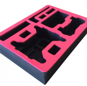
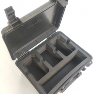
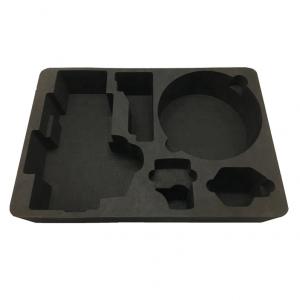
• The part fits but with slight clearance around it: use EVA, IXPE or EPE foam as a locating insert, solving positioning and cushioning in one step.
• Several different products in one tray: foam divisions and die-cut slots made to the actual size of each cell are more flexible than changing the moulded layout.
• Irregular, thin-walled or easily scratched parts: vacuum-formed (PS / PET) or thermoformed inserts that enclose the part completely.
• Where the whole tray must pass through water or air but small parts must not move: foam with cut-outs that locate the parts, with the openings aligned to the base pattern.
• Consider a new mould only when the existing specification is clearly unsuitable — not by entering a new-tooling process from the outset.
8. When new tooling genuinely enters the discussion
Yufa screens existing moulds for a close specification first to help customers avoid unnecessary tooling. This is a screening sequence, not a promise — in practice a few situations do push a project towards customization:
• The existing usable internal size clearly will not accommodate the product, or it only just fits and the loading/removal method then fails.
• No combination of cell count and clear cell size among the existing 7 models comes close.
• A specific locating, retaining or poka-yoke feature is required, and the volume is high enough to justify the tooling investment.
Only in these cases is tooling worth discussing. Otherwise, looking for the answer among the existing 51 models is usually faster and cheaper.
9. Surface resistance must be confirmed model by model
Trays likewise cover two material families, with the resistance range bound to the model: ESD PP alloy with a surface resistance of 10⁴ – 10⁸ Ω (21 flat trays + 3 divided trays), and ESD PP with 10⁵ – 10⁹ Ω (23 flat trays + 4 divided trays).
The size spectra of the two materials do not completely overlap: PP alloy covers external lengths of 225–960 mm and PP covers 150–720 mm, and even in the overlap there are almost no models of identical size. Choosing a material therefore usually means choosing a size band — looking for a size within the band that the available material covers is faster than picking a size first and asking about the material afterwards.
Until a TDS or test data supports a claim, conductive, permanent ESD or a specific standard number should not be used as the main marketing message.
10. Let the product code carry the inquiry
Once a close specification is found, sending the code to Yufa is all it takes to move on to confirming the usable internal size, tray depth, base pattern and foam solution. Each existing code already states the category, material segment, external size and key structure:
|
IMT-PPA-495-495-33 Injection-moulded tray | ESD PP alloy | external size 495 × 495 × 33 mm | rated for 150 °C oven baking IMT-PP-380-310-20-HP Injection-moulded tray | ESD PP | external size 380 × 310 × 20 mm | -HP fully perforated IMT-PPA-400-325-29-D20 Injection-moulded tray | ESD PP alloy | external size 400 × 325 × 29 mm | -D20 twenty-cell division |
A product code shortens the communication path but does not replace project confirmation: clear cell size, tray depth, base pattern and resistance grade still have to be checked against the specific model before ordering.
11. Frequently asked questions
Q: Do we have to open a new mould to buy an ESD tray?
A: Usually new tooling does not have to be the first step. The 51 existing specifications cover the great majority of routine scenarios with external lengths of 150–960 mm and tray depths of 16–100 mm; customization is discussed only when the usable internal size, cell count or structure all fail to match.
Q: Can a divided tray be supplied with only some of its cells?
A: The existing cell counts are 4, 6, 8, 10, 20 and 80; any other count needs a new mould. If you simply do not want to use every cell, filling the surplus cells with foam or a die-cut divider is faster than modifying the mould and does not change the overall tray size.
Q: Can injection-moulded trays be supplied with a lid?
A: The tray series is not supplied with lids.
Q: Does perforation affect ESD performance?
A: The resistance range is set by the material family (PP alloy 10⁴ – 10⁸ Ω, PP 10⁵ – 10⁹ Ω); the base pattern changes the base structure, not the material grade. What perforation really affects is load capacity, wash-through and whether small parts fall through; for processes with cleanliness requirements, deburring of the hole edges must also be confirmed.
Q: Can the trays go into an oven?
A: Two current models are rated for 150 °C: 495 × 495 × 33 and 960 × 600 × 35. The temperature resistance of all other models has to be confirmed per project, and these two figures must not be applied directly.
Q: Can the trays be stacked?
A: They can be stacked, but the existing tray walls have no dedicated stacking stop, so stability at height varies by model. Where several layers are involved, raise the number of stacked layers and the total stack height together and we will confirm per model.
Q: How do I choose between a foam tray and an injection-moulded tray?
A: Decide by the number of reuse cycles and the cleaning method. Injection-moulded trays withstand repeated circulation, can be washed and hold their dimensions, suiting long-term loops. Foam (EPE / EVA / IXPE) costs less and conforms completely to the product shape, suiting single-use or low-frequency handling and the protection of irregular parts. The two can also be combined: the moulded tray as the frame, foam as the insert.
12. How to start the selection
If a close specification has already been identified, simply send the product code and the estimated quantity; if not, provide the following to Yufa:
• Product dimensions, or the usable internal size / clear cell size you require
• Loading quantity and weight per part
• Application: line transfer, storage, washing and drying, or oven baking
• Whether dividers, foam inserts or die-cut liners are needed
• Target ESD requirement and any other mandatory conditions
|
Send these points to Yufa and start from the existing moulds. We screen the existing moulded specifications for the closest option first and confirm the usable internal size, tray depth, base pattern and foam solution in the same pass, rather than pushing the project to new tooling at the outset. |